|
|
 < Back << Kartbuilding Home
Below is the 6th Drawing from the total of 21 in this complete set of Kart Plans.
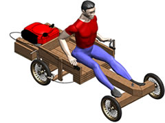
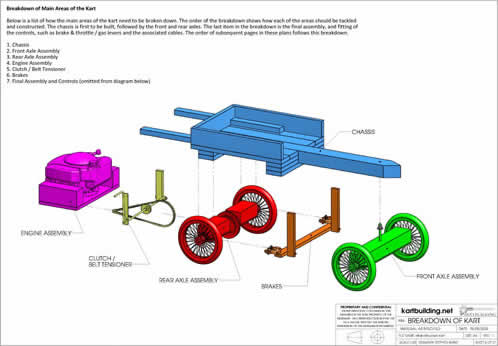
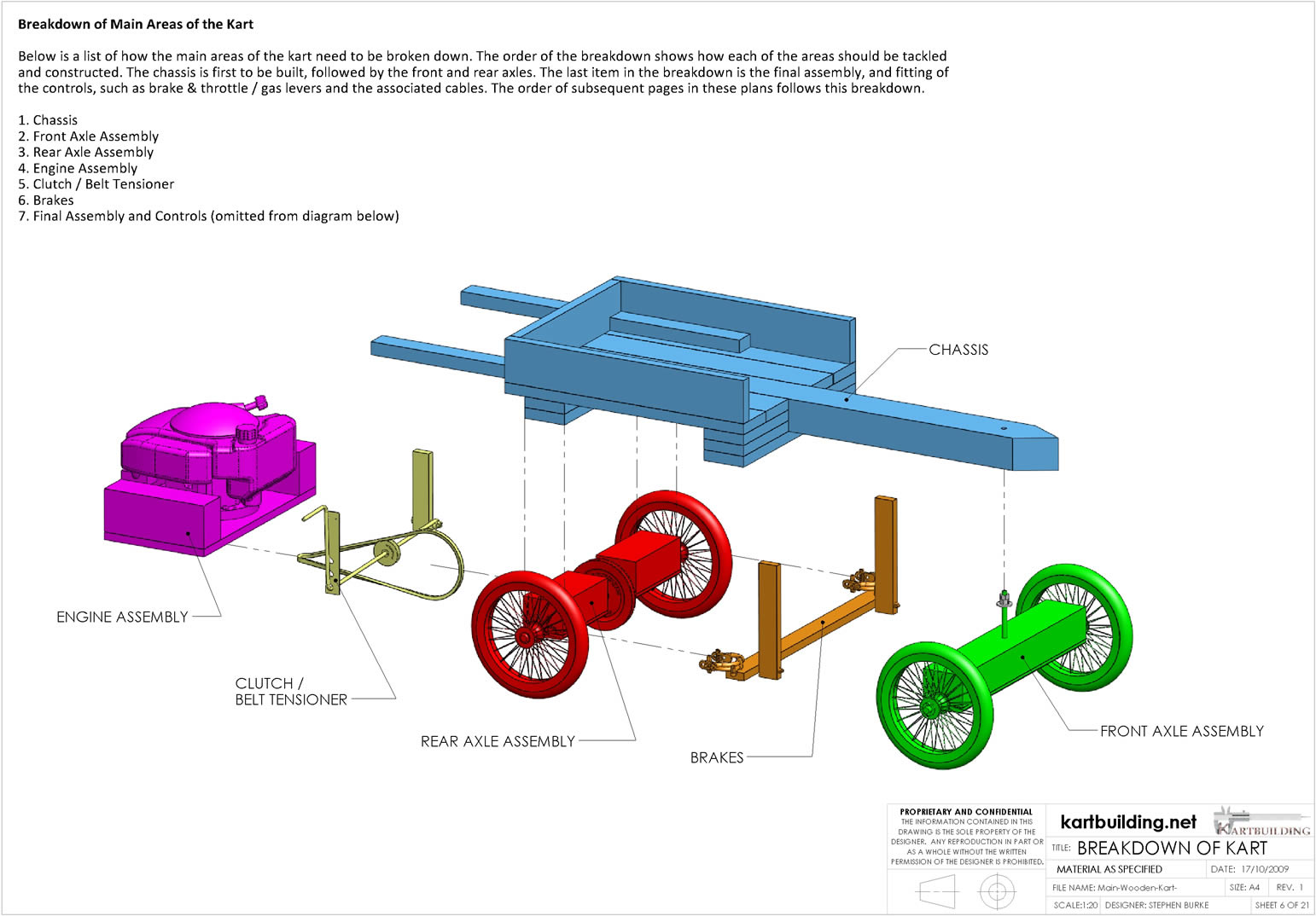
This drawing shows the main areas involved in building this engine powered wooden go-kart. Each of the areas are sequenced correctly. The chassis is first to be made. Then the Front Axle, then the rear axle. This results in a "rolling chassis" which is made at this stage. The wooden go-kart can be used as a push go-kart at this stage! When your dad or friend gets tired pushing the kart, you can move onto the 4th area, the Engine Assembly. The engine assembly involves bolting the lawnmower engine to some plywood which can be screwed in turn to the chassis. More details on all this can be seen later in these drawings. Once the engine is in place, the driving belt must be fitted, and finally the brakes and controls need to be completed. Each of the areas are seperate and distinct. You could do each area over a weekend.