Pedals for the Racing Kart...>
The Pedals for this Racing Kart are very simply made, nothing fancy, but simple and effective.
For this Racing Kart, I have a motorbike engine with a manual clutch, and as a result a clutch pedal is needed. So for this kart THREE pedals are required, (from left to right on the kart) A Clutch Pedal, A Brake Pedal and An Accelerator Pedal. The pedals are arranged the exact same as in a Car, i.e. the clutch is on the left, operated by the drivers left foot, while the Brake is in the middle with the Accelerator on the far right and both these pedals are operated with the drivers right foot.
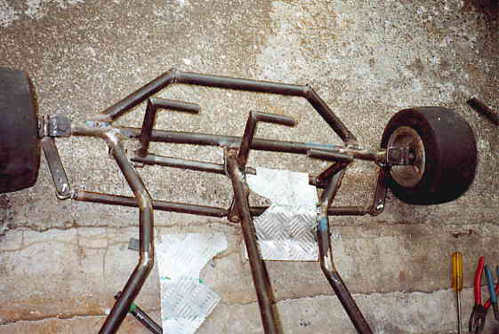
The above picture is how the pedals look on the finished Racing Kart. Of course there is a bit to do before the three pedals are made and mounted as in the above picture.
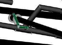
Measurements for the individual pedals are indicated on the picture below.
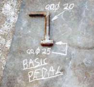
The pedal is made from two different diameter tubing's/ piping. The pivot (bushing) part of the pedal is made from 25mm (1") O.D. (outside diameter) tube/ pipe. The L shape part of the pedal is made from smaller 20mm (3/4") O.D. tube/ pipe. I would have liked to have the L shape in one continuous piece of pipe/ tube bent properly, however I had to make do with what I had, so I cut all the pieces and welded them together to give the above L shape pedal. All materials used was mild steel tubing. If I had a lathe, I would have made nylon or brass inserts for the pedals to pivot/ rotate smoothly, however mild steel had to suffice.
The exact measurements and sizes of the pedals and their layout is shown next.
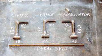
All the three pedals pivot/ rotate on the 20mm (3/4") O.D. pipe/tube Pedal Shaft. The pedals are positioned along this pedal shaft to suit the driver. The layout remains the same, on the first picture on this page, one can see that I have positioned the clutch pedal on the left side on the Steering Column and the brake and accelerator pedals are on the right side of the Steering Column. The individual pedals are located, kept in position from moving over and back on the pedal shaft by means of Split Pins and washers.
The procedure for securing the individual pedals is:
Position the pedals along the pedal shaft to suit the driver, the brake pedal may have to be further away from the accelerator pedal if the driver has wide shoes. A washer is place on either side of the pedal on the pedal shaft. A hole is drilled through the pedal shaft close to the outside of the washers. A split pin (a nail will suffice) is inserted into the hole keeping the washers and pedals in position along the pedal shaft.
Ideally the pedal shaft should be bolted to the chassis/ frame at either ends, however I spot welded the pedal shaft to the chassis quickly as I said to myself that I could always grind off the weld if I had to.
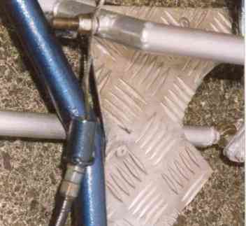
When all the pedals are in position and secure, the next item on the agenda for the pedals was Pedal Stops. These are simply pieces of metal (8mm solid steel round bar) which are secured to the chassis and prevent the pedal from been pushed too far forward by the driver and from coming too far back to the driver. The Pedal stops for preventing the pedal from being pushed too far back are not essential as with the clutch, brake and accelerator pedals the limit to how far the pedal can be pushed is the amount of freedom in the brake/ clutch and accelerator/ throttle.
As can be seen from the above picture the pedal stops are easily made and bent into a L shape. The end Pedal Stops (pieces preventing pedal from going too far forward) aren't essential, however the start Pedal Stops (pieces preventing the pedal from coming back too far) are needed, otherwise the spring will pull the pedal back too far.
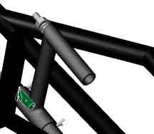
Now with working pedals, the last thing to do is to make provision for attaching the cables to the pedals. Look at the next picture and see the bolt in the horizontal position welded to the pedal.
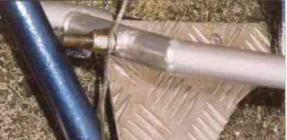
In the above picture, there is a bolt welded to each of the pedals. In the bolt there is a 3mm hole (or whatever the thickness of cable is) drilled in the bolt. The cable is fed through this hole in the bolt. A locknut is then screwed onto the bolt and tightened up on the cable securing the cable to the pedal. The cable can easily be readjusted by loosening the nut and then tightening the nut to finish. However this only takes care of the inner cable that does the work. The outer sheathing, covering of the cable MUST be secured stationary to the chassis, so that in effect the pedal will pull the inner cable out of the sheathing/covering.
To finish up keep grease and oil up all the pedals. If as I have, used mild steel bushings without brass/ nylon inserts grease and oil up all the pedals regularly.
The pedals I have made and that are shown here are a basic simple design that work perfect for my kart, of course you can design your own, more imaginative pedals with rollers etc. for ones feet to operate smoothly on.
Return to Main Racing Kart Plans Page