Step1:
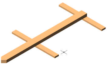
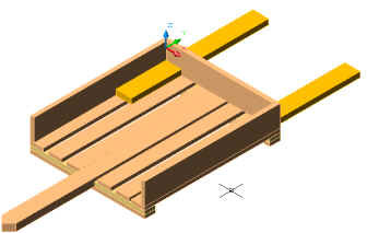
Obtain the main member for the middle of the chassis 50mm X 70mm X 1400mm. (The one with the Pointed front)
Using two pieces of 25mm X 50mm X 500mm long attach them (nails/ screws) to the main chassis member as in the picture below. One goes at the end of the main member and the other member goes 700mm in from the rear/ end of the main member)
Exact dimensions for members are at the following page: Chassis.htm
This is what the chassis should look like:
Step 2:
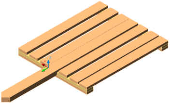
Obtain four small pieces of wood to act as filler pieces for boards later on. These filler pieces are nailed/ screwed to the two runners at 90 degrees to the main chassis member. They can be seen in the next picture in the lighter color. These filler pieces are 25mm thick which will leave the 25mm boards to be fitted next flush with the main chassis member. The main measurement here is 25mm thick and they are to be put on either side of the main chassis member.
Step 3:
Fitting of the main floor boards for the chassis. Likewise two pieces of 25mm thick plywood can be put on each side to do the same purpose. in the picture below the boards are not tight together as this is to show the boards clearly. Either boards nailed/ screwed to the filler pieces fitted tightly together (opposite to picture) or two pieces of plywood can be used to provide a smooth level top surface for the chassis.
Step 4:
The main two arms for holding the engine must now be fitted to the chassis. These arms are 75mm wide (or 50mm) X 50mm thick X 650mm long and are again nailed/ screwed to the top of the chassis as in the picture below.
Step 5:
The side pieces and rear piece for the main chassis must now be fixed in place. The side pieces will be used later on for mounting the accelerator and brake lever as can be seen in the overview of the plan HERE. Measurements are up to one's own personal discretion, a basic guide is to have the boards 20mm thick by 120mm high and 700mm long.
That's all the steps involved in making the main chassis.
Next is a picture of the chassis from above with the engine roughly drawn in showing the positioning and working of the engine.
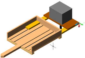
As you can see from the above picture, the engine is mounted on it's own separate base board (dark brown in above pict.). This base board is then clamped to the two arms. I used four "G Cramps" for holding the base board to the two arms with I was messing around with the drive belt, making life easy to tension the belt and adjust the engine position.
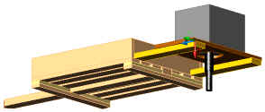
This is an underneath view of the previous chassis with engine.
A small pulley wheel is mounted on the vertical drive shaft of the engine.
A large pulley is attached to the center of the rear axle, as can be seen in the picture below. The "Rear Axle Assembly" is shown in this next picture and the following pictures.
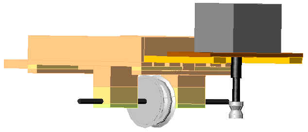
To explain the above picture using colors of the above picture. The rear busing assembly holding the rear axle is held between two pieces of wood - a thin 25mm (green) piece and a 50-75mm (lighter green) piece of timber. This bushing assembly as shown and explained on the bottom of THIS PAGE is attached to the chassis via the bulky piece of timber attached to the underneath of the chassis.
The two pulleys are then connected up via a "V Belt" drive belt.
I hope this page clears up a lot of the questions surrounding
making the chassis for this Basic Wooden Kart. I hope to have the rest of the
pages written up over the next while (month or two) for this Basic Wooden Kart
section. If you have any questions before that, then drop me a mail with your
question to 
Return to Main Page of Basic Wooden Kart Plans