|
|
 << Kartbuilding Home
While there are already plans on kartbuilding.net to make a wooden go-kart, people have often asked about having a steering wheel on their wooden go-cart. Also people might like a more user friendly, safer wooden cart for younger kids to play with (the other wooden go-kart used spoked wheels, had foot steering and was designed for an older child).
This cart is designed as a "push" cart and best suited for grassy areas. Unlike the other wooden kart, this one cannot be easily adapted to provide mechanical drive with an engine/motor.
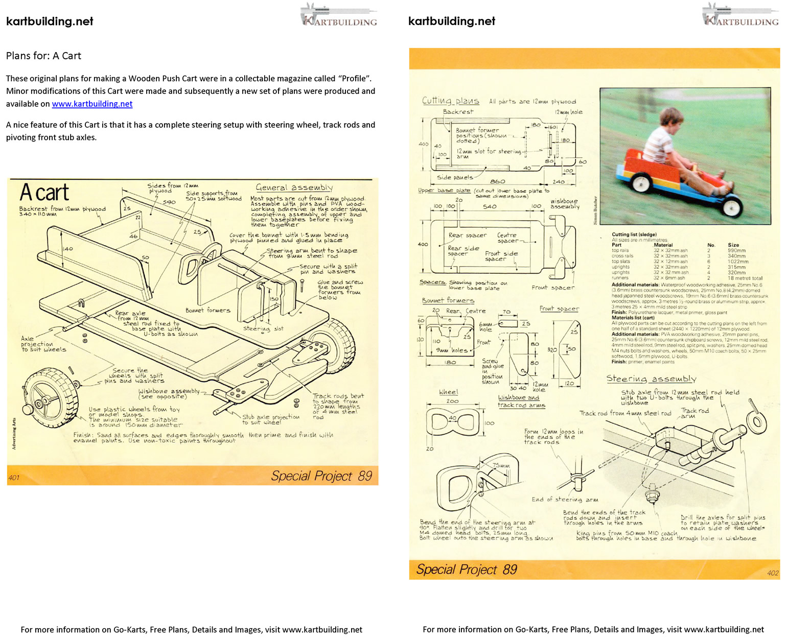
The idea and initial design of this cart was originally published in a DIY Collection of Magazines called "Profile", many years ago (approx 20 years). For quite a while I wanted to build upon the original plans, adding a few extra details (brakes) and making it a little easier (hopefully) to follow. The wooden cart looks well, has a nice steering setup, and is easy to build (it's actually the easiest of all the carts on www.kartbuilding.net to make.
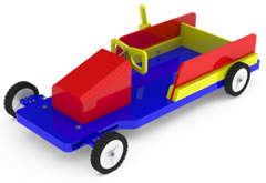
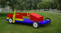
The colours of paint used (red, blue, yellow) make the cart stand out, nice to look at and "fun" for children. The four wheels are plastic and can be obtained from an old lawnmower or bought off the shelf.
Most vehicles/toys that children play with have steering wheels. The steering wheel in this cart comes as a welcome addition, although it requires a bit of extra work in setting up. The brake is an extra addition also, and was not included in the original set of cart plans.
This cart should be easy to build, take approximately a weekend to make, and be fun for children to drive.
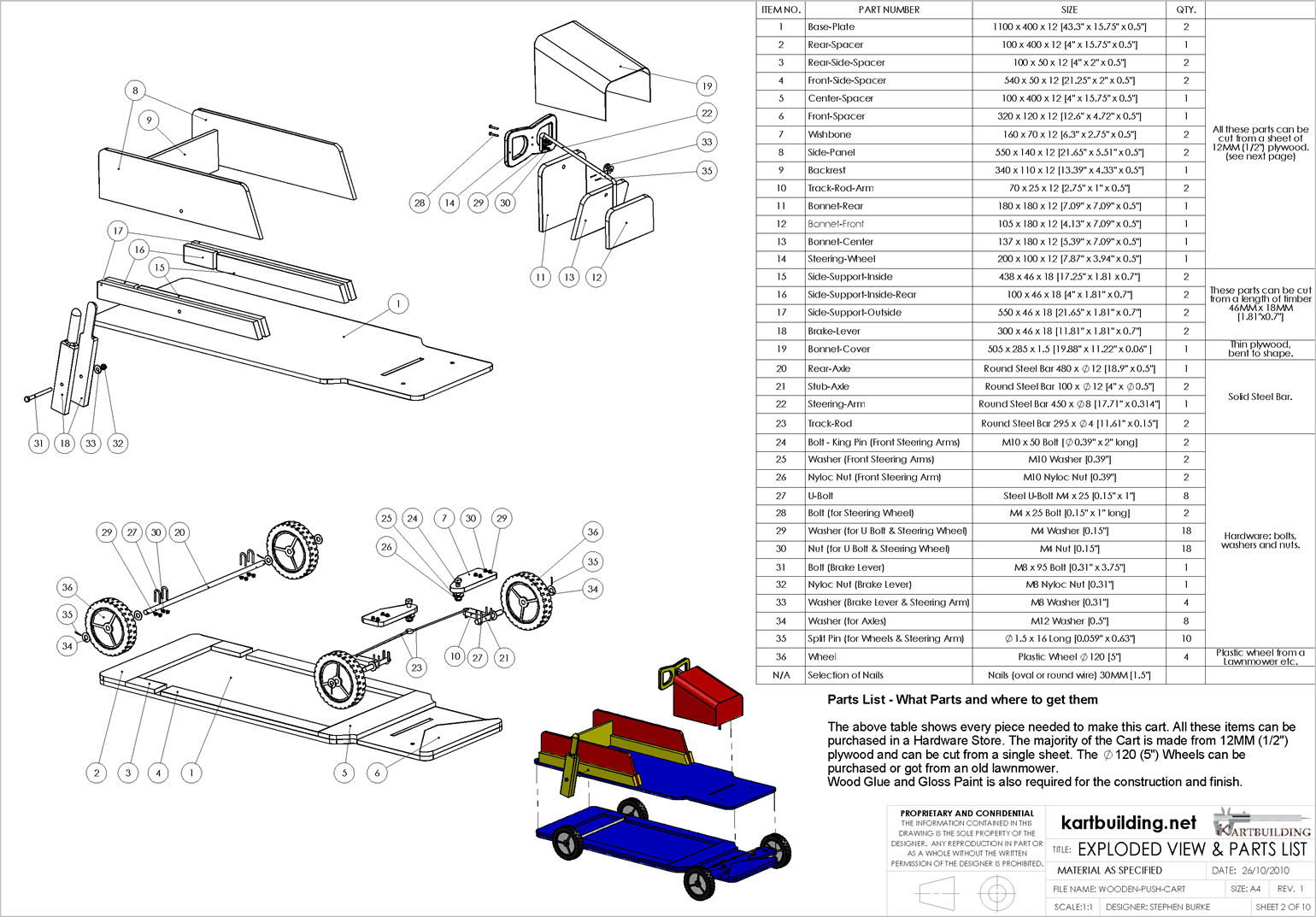
All parts used on this cart are commonly available. The main carcass of the cart is from a 1/2 sheet of Plywood (12mm or 0.5in thick). Extra 2"x1" planed timber (18x46mm) is used for extra support around the Upper Chassis. Make sure the plywood is of good quality, and not splitting or coming apart. It is unadvisable to substitute the plywood for "pineboard" (pine laminate sheeting) as this would not be as strong in the cross grain direction. Parts such as the "Track Rod Arms" (10) will need to be strong and sturdy.
A trip to a local hardware store will be required to get all the parts required. It would be very difficult to make this cart from off-cuts. At the least, a 1/2 sheet of plywood is required. Nails and glue is used throughout, however you can use screws if you like. With modern day battery operated cordless drills, putting the parts together would be quicker than nailing. Glue is used throughout to make for a permanent connection.
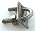 U-Bolts are used to connect the axles to the chassis. Either use large washers or a steel plate (if supplied) to tighten as much as possible. The local hardware store should be able to provide the solid round steel bar for the Axles, Steering Arm and Track Rods. If you ask nicely, they may be able to cut the lengths required for you, saving you from having to buy a full length.
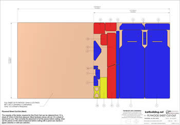
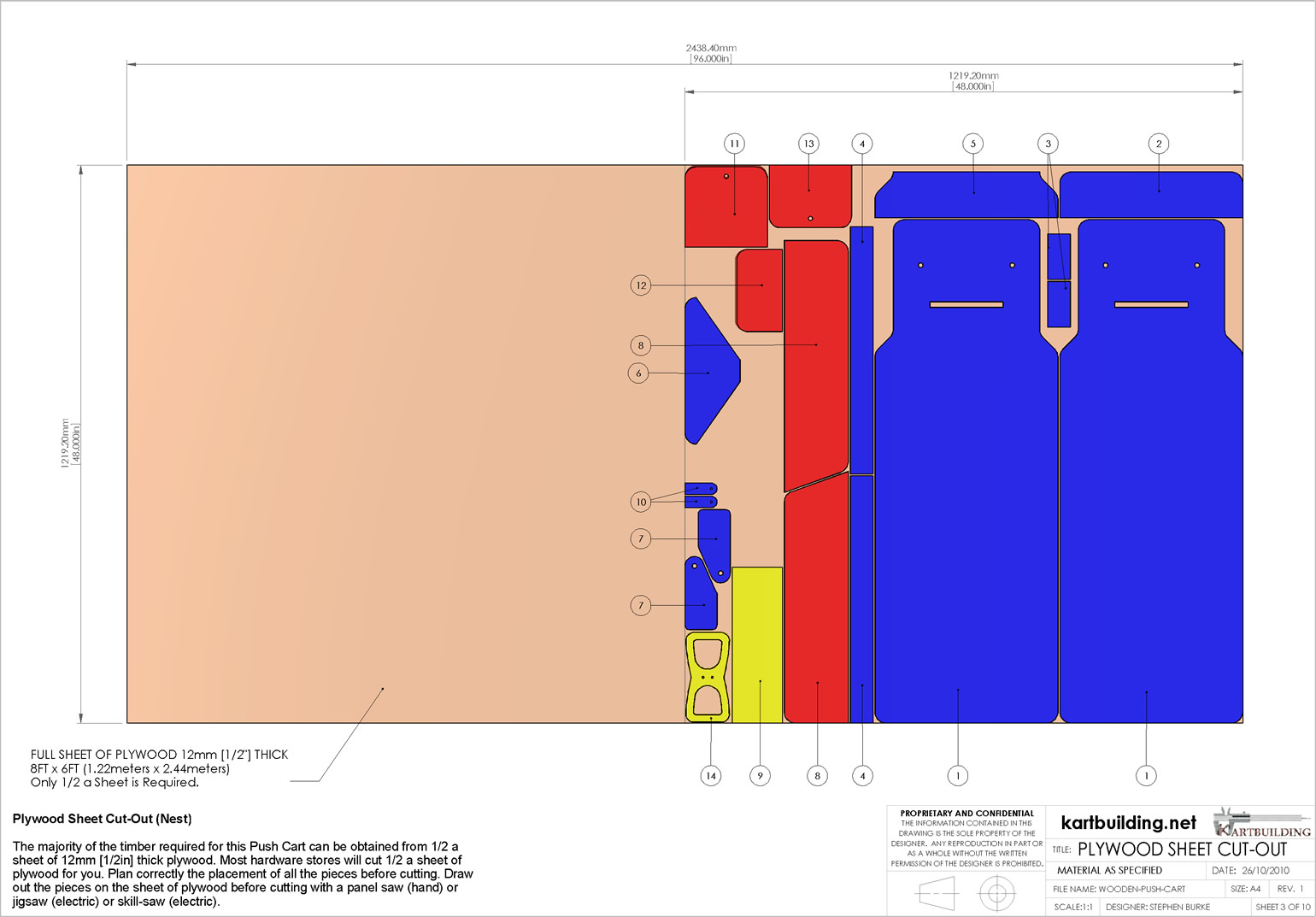
 This drawing shows that all the plywood parts can indeed be cut from half a standard sheet. Care must be taken to reduce waste as much as possible. When the half sheet is purchased, draw out in pencil all the required pieces.
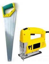
If available, an electric jigsaw will make cutting out the pieces very quick and easy. However, with a little patience and care it would be more than possible to use a hand-saw to cut out all the pieces required.
The steering wheel may take a little extra time to cut out. It may involve drilling a series of small holes to cut out the "D" shapes, and then a lot of sanding and smoothing. Wrap some coarse sandpaper around a round bar/handle (handle of a brush etc.) and use this to help form the "D" shape.
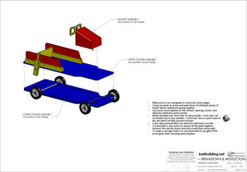
There are three main areas to the Cart. The Lower Chassis, Upper Chassis and the Bonnet. The final assembly of these three areas can be seen in the last drawing (Drawing 10).
 It would possible to paint the individual pieces before nailing/screwing them together. Only paint the "external faces" of the timber, and not the faces which are to be nailed/screwed & glued together. Mark with a pencil what faces are to be attached. You could get a youngster to paint some of the parts as you work. This is optional however, and the cart can be painted at the very end if you like either.
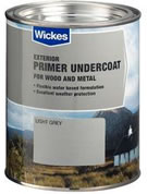
Primer paint for external wood, should be used firstly and then a gloss metallic coloured final coat of paint. Be careful of your choice of paint as you do not want it coming off on a youngsters hand on sunny days etc. You also want it to protect the cart in case of rain. Its possible to use a "Stain" which would serve as a primer and final coat, however it is difficult to get different colours (apart from brown and green).
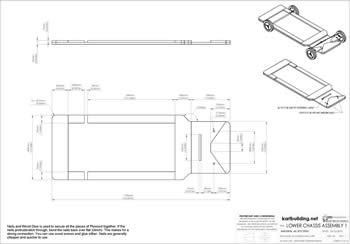
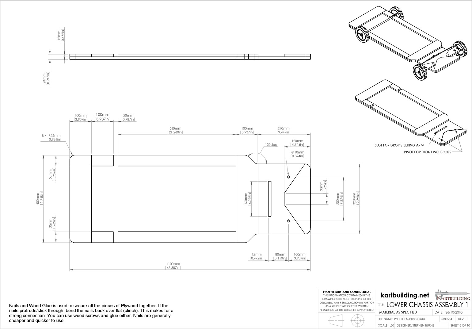
This stage involves just making the Lower Chassis. All the pieces required are obtained from the 1/2 sheet of plywood.
The slot shape for the Steering Arm will have to be carefully cut with a saw. A chisel (mortise or similar) can be used to remove a portion of material to fit in a small saw. It would also be possible to drill a series of large holes and then to remove the rest of material with a hand saw.
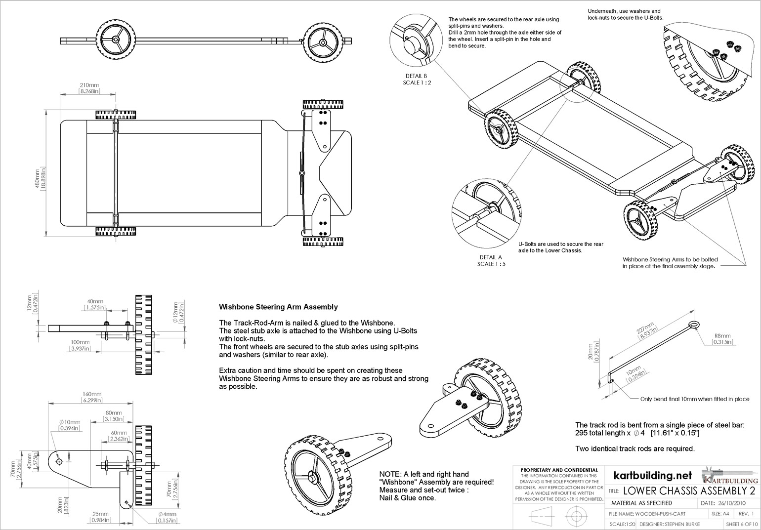
There is quite a bit of work involved in this step. The most important part to get correct and strong is the Steering Arms (Wishbones). NOTE: a Left and Right hand version are required! So, be careful when attaching the track rod arm, stub axle and u-bolts.
Holes for the u-bolts will also have to be made. It would be best to borrow or use a drill for this, either a cordless battery operated drill or an electric one. Make sure to tighten the u-bolts fully on the front axles. This would be one of the weaker areas of this wooden push cart.
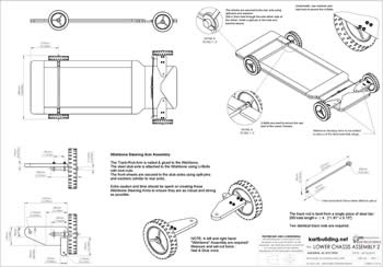
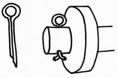 The wheels are held in position with "split pins" and washers. This involves drilling a small hole right through the center of the round steel bar (1 or 2mm diameter). Once the hole is drilled, a split pin, or even a small nail is inserted with the top and bottom bent over so the pin/nail does not come out. Make sure to apply some oil and grease to the axle before placing the wheel on.
The track rod needs to be bent to shape. This will require a pliers, and if available a Vise or hand held vise-grips. Note: the last piece of the track rod should only be bent after it is in position. This is to prevent the track rod from coming up out of the track rod arm.
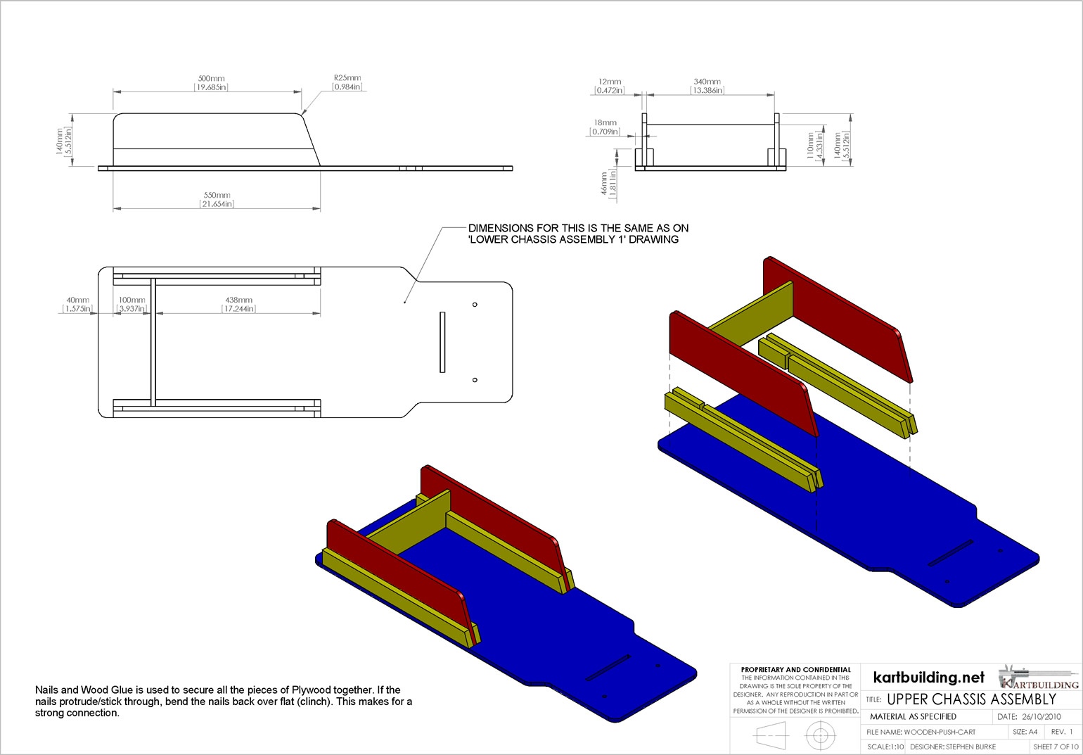
 Once the Lower Chassis is complete, the Upper Chassis is straight forward. All the measurements for the main "base plate" are in previous drawings (Drawing 5). Again, screws can be used instead of nails to secure all pieces together. If nails protrude or stick out, bend the nails flat over. In the case of screws, the end of the screw will have to be cut off and ground flat if it sticks out.
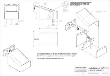
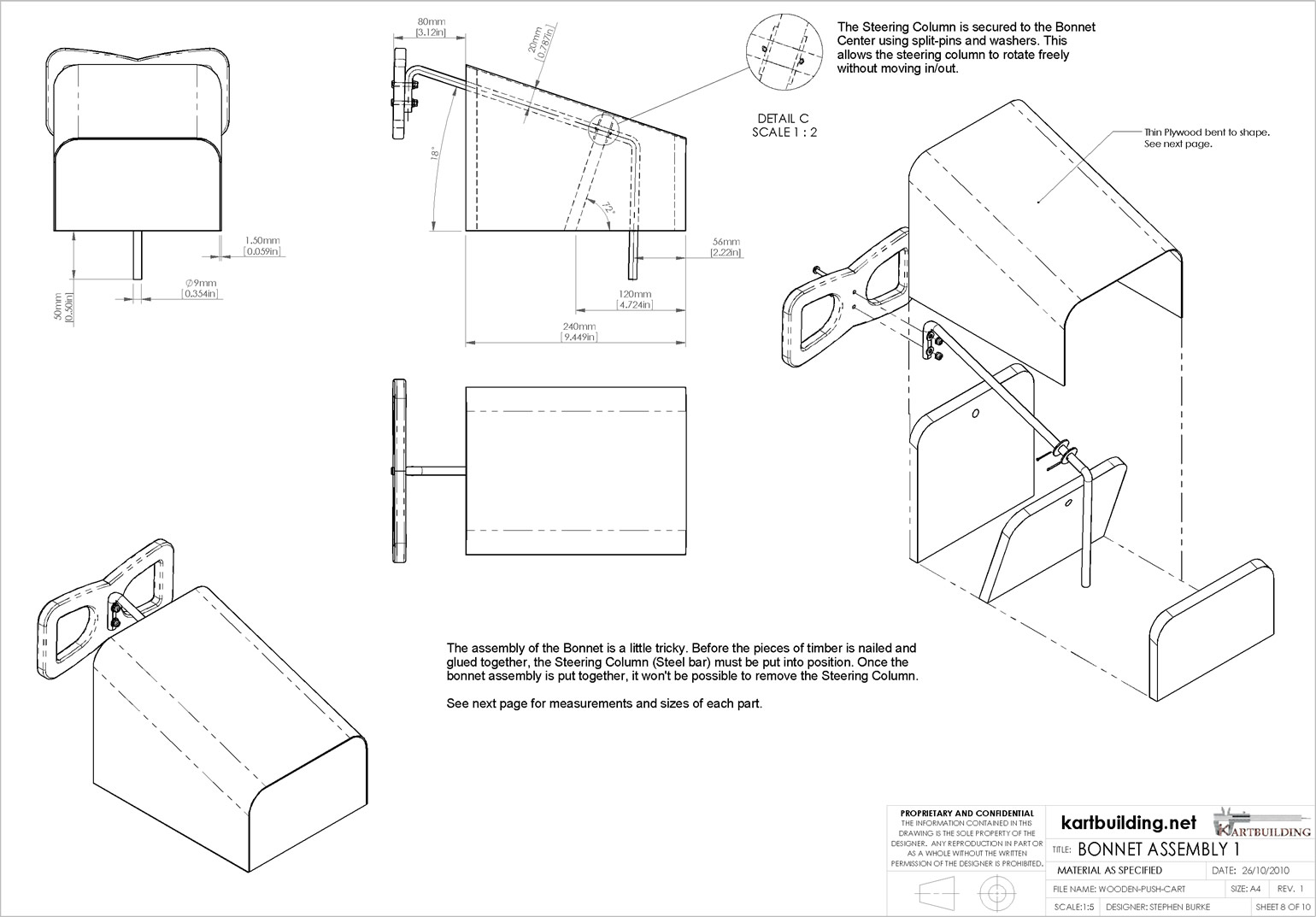
The Bonnet Assembly is one of the most tricky areas of this wooden cart. The sloped shape of the bonnet makes things difficult, especially the shaping of the cover, and also the steering arm and how it pivots. It would make things easier if the steering arm was horizontal, as the Middle-Bonnet piece could be positioned vertically with a simple hole. Also the hole in the Front Bonnet piece must be drilled at an angle to achieve a true correct shape.
It would also be a good idea to use some off-cuts from the 1/2 sheet of plywood to secure the 3 pieces of the bonnet together firstly. The cover/lid of the bonnet which needs to be bent to shape, should be left until last. NOTE: the steering arm must be fitted in place before securing the three bonnet pieces (Bonnet-Rear, Bonnet-Front, Bonnet-Center from Drawing 2).
You don't have to worry too much about the position of the Steering Arm, as the bonnet assembly can be positioned to the Upper Chassis afterwards.
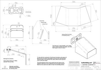
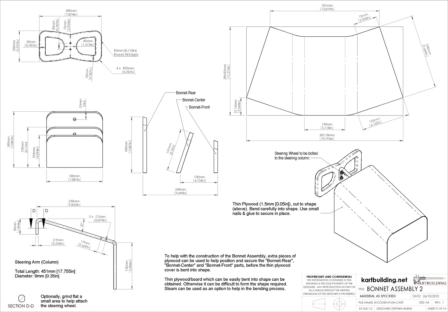
This drawing shows each of the pieces required to make up the bonnet assembly. As mentioned previously on Drawing 3 explanation above, the steering wheel will take a little work to get correct and smooth.
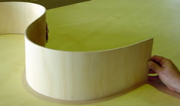 It is possible to get "bending plywood" or "flexible thin ply". This will make things much easier to form the top cover of the bonnet. It would be very difficult to bend normal plywood into the shape required. Small nails and glue will be required to secure the cover in place.
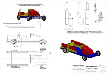
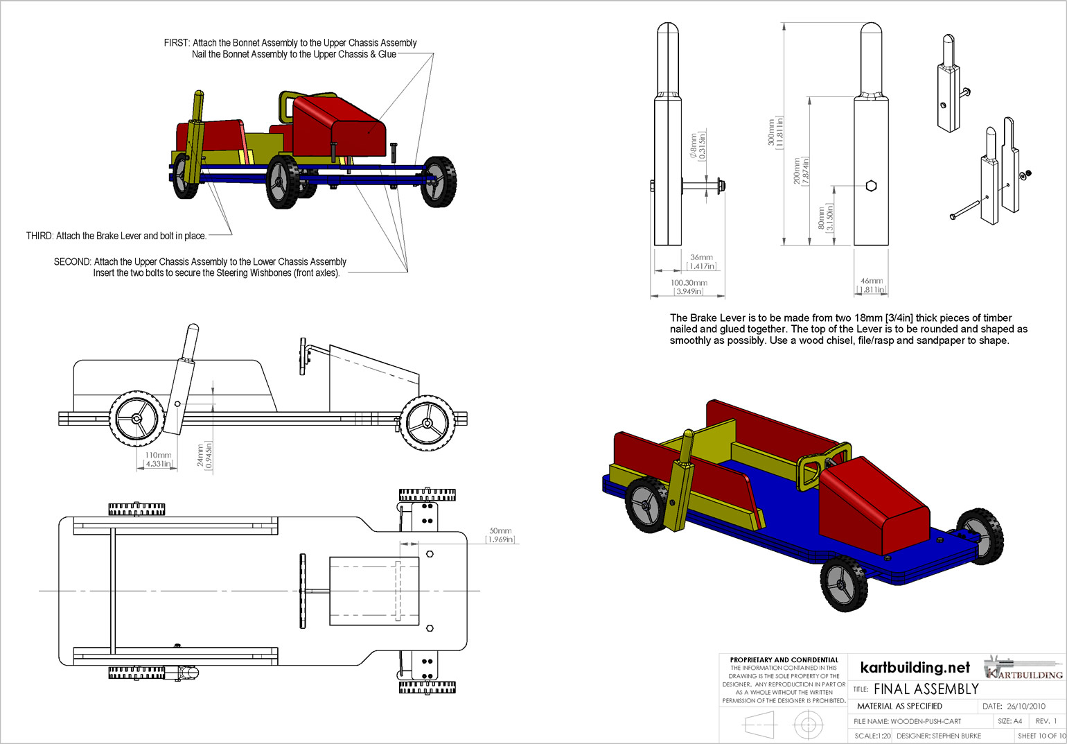
Once the main three sections of the cart are made, the final assembly is easy. The Bonnet Assembly must be attached to the Upper Chassis Assembly, making sure that the Steering Arm lines up correctly with the square slot. Make sure the steering wheel turns freely when lined up with the square slot (see dotted rectangle in bottom left plan view in Drawing 10).
The Upper Chassis is then secured to the Lower Chassis. Make sure to insert the Steering Wishbone arms in place and secure with bolts. It would also be advisable to apply some oil and grease (or silicone lubricant which will not attract dust) to the pivoting steering arms, as this will make steering easier.
The final step is making and fitting the brake lever. The brake lever is a simple piece of timber rounded and shaped at the top, which pivots against the rear wheel. Note: this brake lever is not designed to provide an immediate stop, but to help slow the cart down gradually. Further adaptations can be done. Another option is to make the brake lever longer, and to have the end rub off the ground as opposed to the rear wheel. This is not ideal on uneven ground and it may leave marks on grass also. Make sure to tighten the bolt attaching the brake lever to the chassis so it is not too loose or too tight.
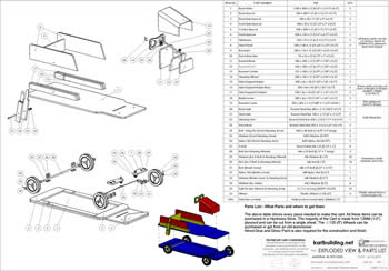
![]() An electronic copy (eDrawing) of the above drawings can be downloaded. Within the eDrawings program, any Item or piece can be measured using the "measuring tool". The exploded view of the cart can be seen. The wooden go-cart can be rotated in 3D - allowing you to look underneath, or from the back etc. A section view can also be obtained using these eDrawings.
An electronic copy (eDrawing) of the above drawings can be downloaded. Within the eDrawings program, any Item or piece can be measured using the "measuring tool". The exploded view of the cart can be seen. The wooden go-cart can be rotated in 3D - allowing you to look underneath, or from the back etc. A section view can also be obtained using these eDrawings.
Download: eDrawing Go-Kart Assembly
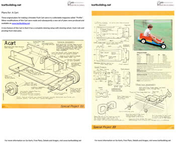
Mentioned at the top of the page was the fact that the initial design of this wooden push cart came from a "Profile" magazine published over 20 years ago and no longer available. The above Drawings hope to make it easier understanding and building this cart while adding upon a few areas (brakes and steering) and making the dimensions more complete. For reference however, the original format of the plans is available on the left.
It seems that nowadays, parents buy children pedal cars, pedal tractors, pedal go-carts etc. Perhaps by having these plans available some people will make a cart instead. There is much more satisfaction and fun in making and using a cart built at home.
Safety: Please note that without adult supervision, this go-cart can be very dangerous, and the Author accepts no responsibility for any hurt or injury caused. This cart is ideally suited for a grass park with no traffic.
Feel free to refer people to this website and/or link from your own website etc.
The Author of these plans and of this www.kartbuilding.net website would be interested in receiving any comments and suggestions. Please use the following email address:

The above drawings were done using SolidWorks. Feel free to contact the Author for any further information.

