|
|
 << Kartbuilding Home
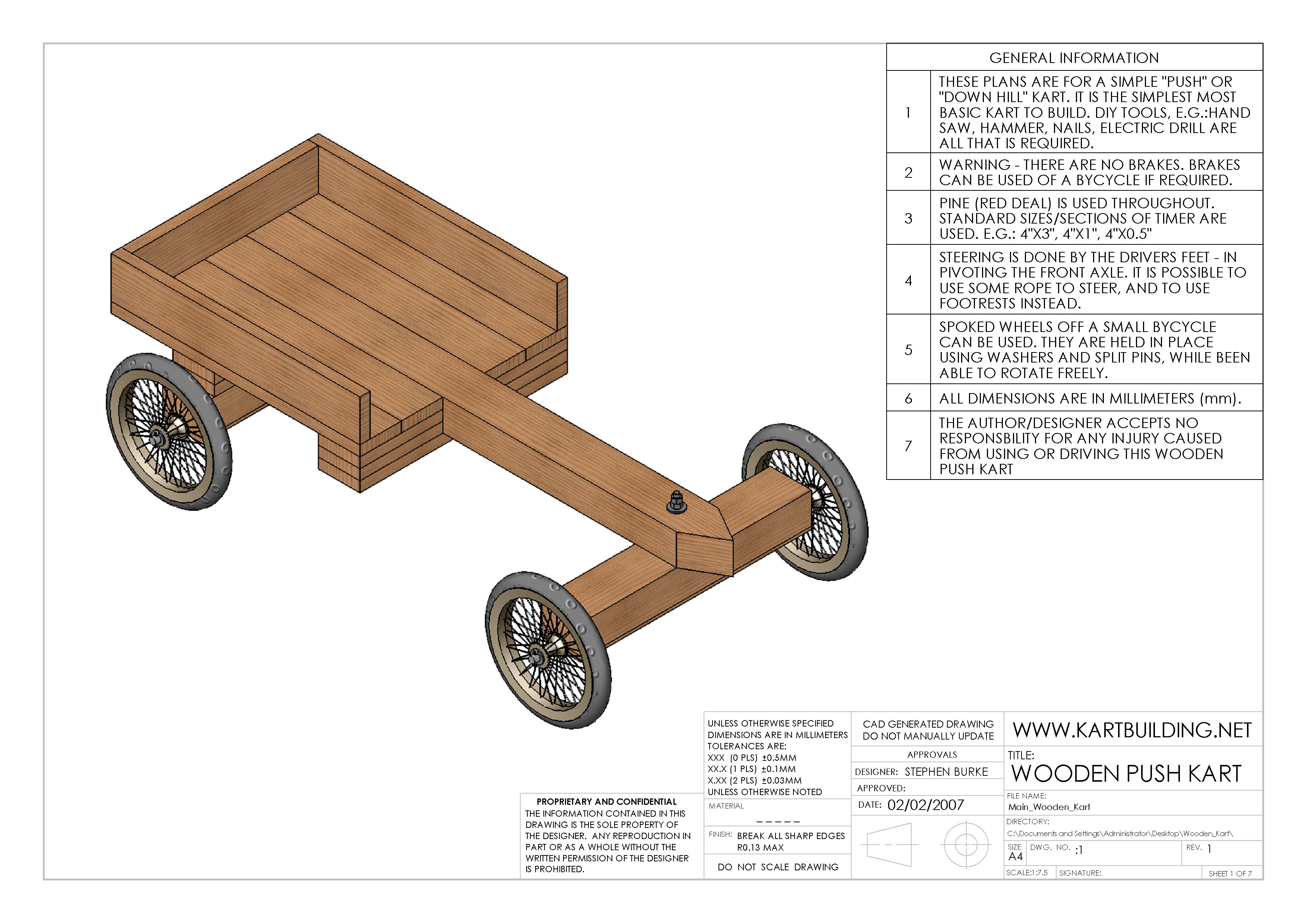
Wooden go-karts, often called go-carts or carts, are simple vehicles which are not self-propelled, threfore someone must push the go-kart and driver, or use the kart for going down hills, hence the prefix "go" is put before the kart. In these plans, spoked wheels are used, as this allows the driver to to turn the wheels by hand, much like on a wheelchair. Normally - the steering mechanism is very simple, and can be done by the drivers feet, or by using a length of rope to rotate the front axle, much like on old stage coaches seen on television. Typically on simple wooden kart, or soap-box-carts, there are no brakes, and as a result - are to be used for slow speeds only. It is possible to include brakes off a bycycle etc., however this complicates the build.
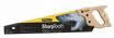

 The simple wooden go-kart, the plans of which can be seen below can be made by anyone. Only simple common tools are required, along with some materials easily found at home, or which can be purchased very cheaply in a DIY (do-it-yourself) , or hobby shop. The tools required to build this wooden kart are: A Hammer, A Hand Saw, An Electric Hand Drill, An Adjustable Spanner, A Measuring Tape/Ruler, and A Metal Hacksaw. The materials required are: 2" (inch) Round Nails, 5" (inch) Round Nails, Planks of 3"x4" timber/lumber, Planks of 1"x4" timber/lumber, Length of 3/4" (15mm) Diameter Round Metal Bar, 4 Spoked Wheels, Range of Washers, Range of Bolts and Nuts and Split Pins.
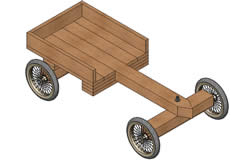
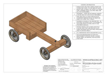
This Drawing shows the Overview of the Wooden Go-Kart. The simplicity of the go-kart can be seen, especially with the basic steering, and the sinmple planks of timber/lumber that are used. 
 The timber/lumber is nailed together using Round Wire Nails. Wood glue could be used, however it is not necessary, and would make it very difficult to dismantle the go-kart. Where possible, protruding nails should be "clinched" to provide extra strength and safety (clinch means to bend over/flatten protruding nails).
Finding/getting the spoked wheels for this go-kart is the hardest part. Once the appropriate wheels are available - making the kart is very easy and simple. Spoked wheels can be obtained of old prams. Pnuematic spoked wheels can be obtained from small childrens bycycles. It can be difficult to fit the Metal Bar/Axles through the center of these wheels, however the axle can be filed down at the end to the required diameter.
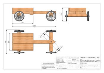
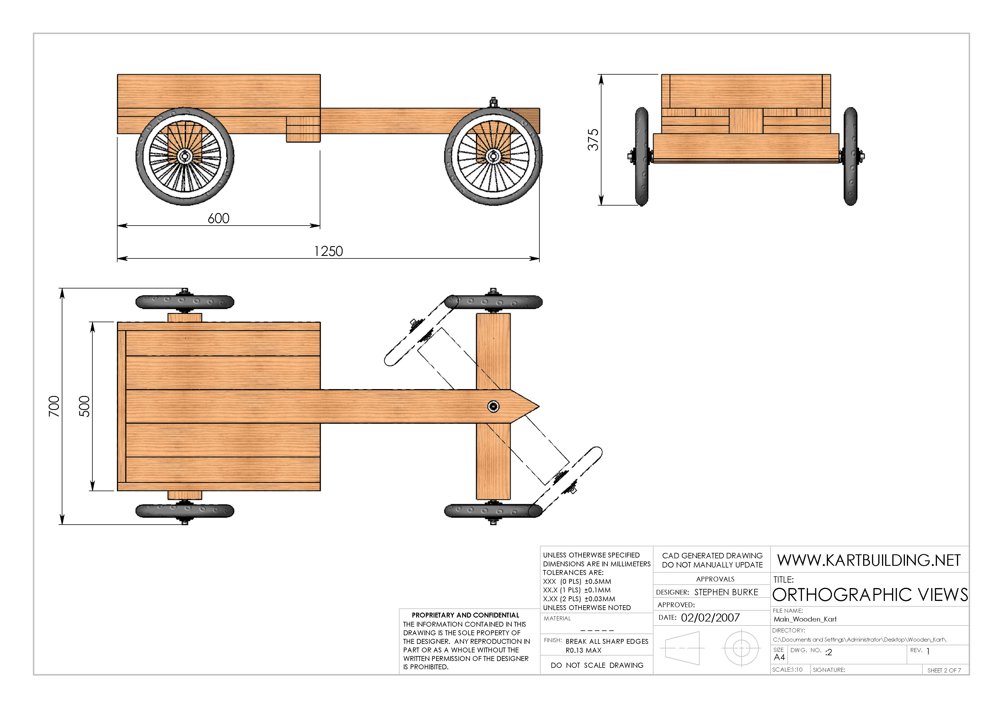
This Drawing shows some of the main dimensions/measurements for the wooden go-kart. The go-kart is approximately 1.2 meters long, by 0.7 meters wide. If required for a smaller or larger person/driver, or if a two-seater go-kart is required, the width and length of the go-kart can easily be changed to suit. The height of the kart depends largely on the diameter of the rear wheels. The larger/smaller the wheels the further/closer to the ground the go-kart is. I suggest obtaining spoked wheels of diameter 270mm.
The steering or pivioting of the front axle can be also be seen in this Drawing. The front axle can be rotated left or right, and can be controlled/ operated by the drivers feet, or by a length of rope attached to either end of the front axle.
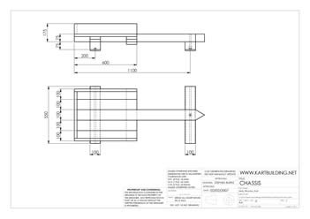
Standard timber/wooden planks of 100mm (or 4") width make up the main chassis. The center chassis member is thicker and longer. The distance between the front axle and the rear of the kart is not critical, however there should be enough room for the front axle to pivot without the front wheels hitting the seating area of the wooden go-kart as seen in Drg 2.
The front and rear axle support members are 100mm wide x 75mm deep (4"x3") x 550mm long. The front axle support member is connected to the chassis at the front via a 12mm Bolt, allowing it to rotate right or left. This 12mm bolt cannot be over-tightened, as the front axle will not turn freely. Instead a "lock nut" is to be used, and in this case, two nuts are used and tightened together locking them, preventing them from loosening.
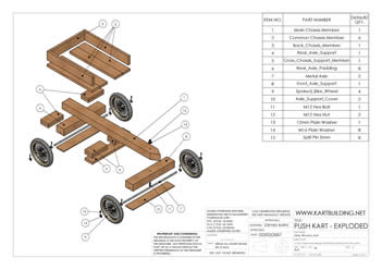
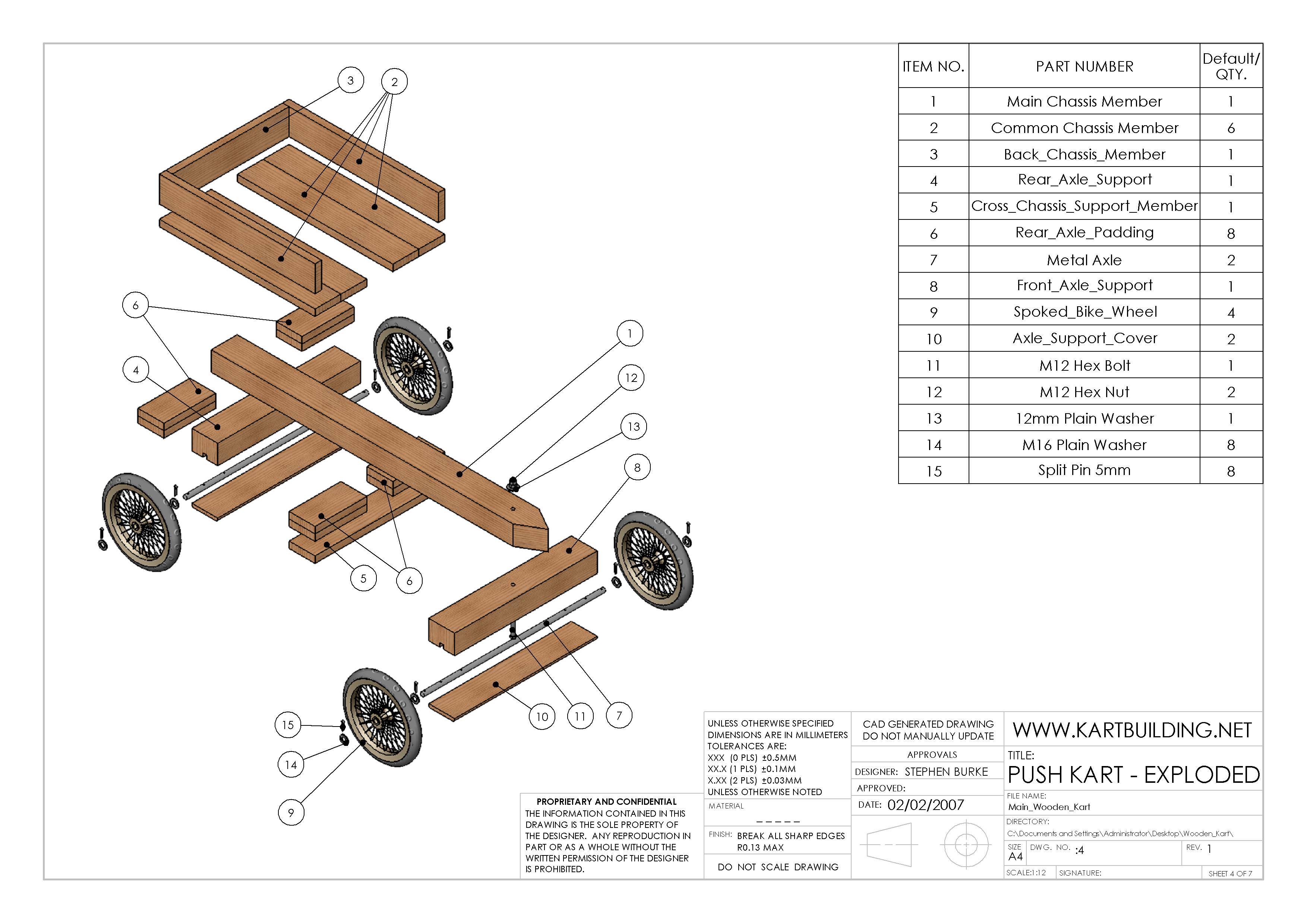
The Assembly of the wooden go-kart can be seen in this Drawing 4. There is a flash animation on the right - showing the disassembly and assembly of the wooden go-kart showing every nut, bolt, washer and piece of timber used to make the kart.
The Front and Rear Axle supports are one of the first pieces to be made. These wooden support pieces, have a groove/ slot to accomodate the Metal Axle securely. As will be seen in later detailed diagrams, there are additional holes in the middle of the Metal Axles to recieve a Round Wire nail to secure them inside the Wooden Support, and to prevent them from rotating or moving from right to left.
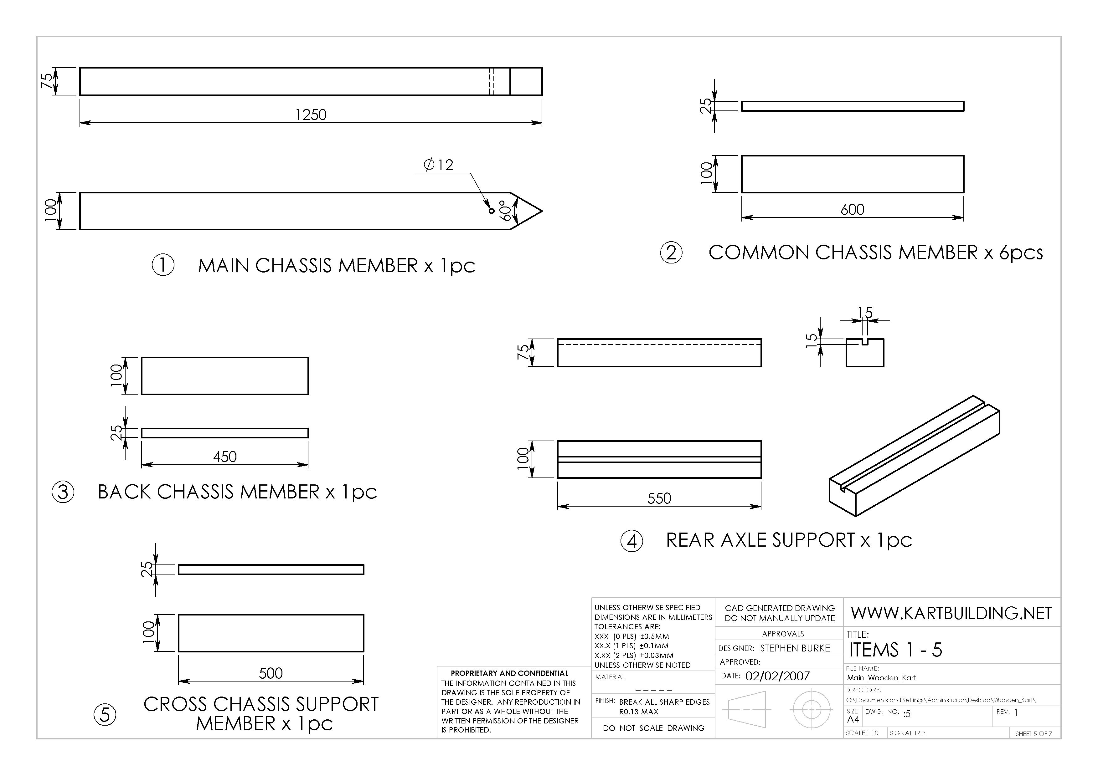
Detailed diagrams of the dimensions and measurements of Items 1-5 as listed in Drawing 4 (Exploded View) are contained in this Drawing.
(1) Main Chassis Member: This is a piece of timber (pine etc.), 100mm x 75mm x 1250mm. The 60degree pointed front end is not essential, and can be shaped when the go-kart is finished and assembled. A front bumper or fender could be placed at this end, instead of the 60degree point.
(4) The rear axle support is made from the same size timer as for the Main Chassis Member. There is however a 15mm x 15mm square groove/slot along the length of this piece. This is to snugly accomodate the 15mm diameter metal axle. There are a few ways to remove this slot/groove:

a: Using a 15mm Mortise Chisel
b: Using a plough plane
c: Using an electric (skill) saw (set the depth to 15mm, making 4-5 parallel cuts)
d: Using an electric drill and 15mm drill bit, drill a series of holes, 15mm deep. Clean up afterwards with any chisel.
(6) The Rear Axle Padding pieces, can best be seen in action in Drawing 4 (Exploded View). Two of these 25mm thick padding pieces amount to 50mm, and sit on top of the rear axle support, on either side of the Main Chassis Member. Longer nails will need to be used, to make sure these padding pieces are secured in place.
(7) The Metal Axles are simply lengths of metal bar, diameter 15mm. These can be obtained from old railings or gates, or can be purchased at a local hardware or DIY store. There are a total of four 5mm holes drilled. The middle two holes, 400mm apart, allow for the Metal Axle to be securely nailed to the Rear/Front Axle Support members. 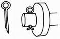 The holes at either end of the Metal Axles are to accept a "split pin", and along with a washer, help to secure the Spoked wheel onto the axle, while allowing the wheel to rotate freely. Grease should be placed on the ends of the Metal Axle where the wheel rotates, as this will prevent excessive wear. More grease may have to be applied after a few weeks of running the go-kart.
(8) The Front Axle Supports are made the exact same way as described above in Drawing 5. With the Front Axle supports however, an additional Counterbore (a large enough hole to allow the head of a bolt to go deep into the timber, underneath the Metal Axle) needs to be drilled. A large drill bit can be used. This is to allow the head of the bolt to go underneath the Metal Axle (otherwise the front metal axle would have to be in two pieces). Make sure that the M12 bolt (Drg 7.) is tightly in place, to prevent it from spinning.
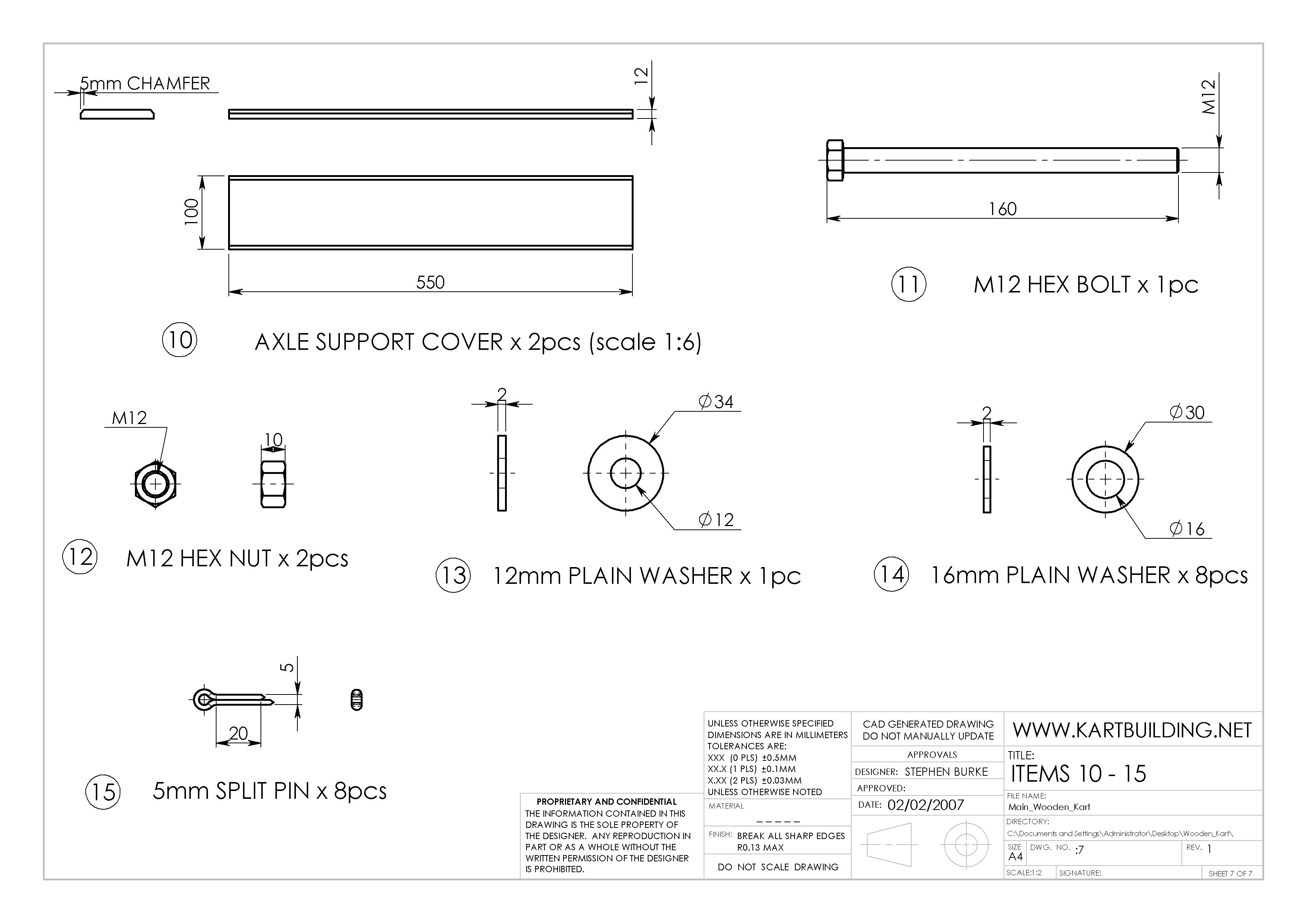
(10) The Axle Support Cover is nailed under both the Front and Rear Axle Support Members. As they serve no structural purpose, they can be cut from a thinner plank of timber (12mm or 1/2") to reduce the weight of the kart. A 5mm Chamfer/bevel can also be added.
(11) The M12 (diameter 12mm) Hex Bolt, Nuts, Washers and Split Pins can be obtained from a local hardware or DIY store. Make sure that the M12 Hex Bolt (this could be a "M12 Coach Bolt either" - however is less common) is held tightly in the Front Axle Support Member (underneath the Metal Axle) to prevent it spinning. Otherwise when tighting the two M12 Hex Nuts - the Bolt may spin.

(12) Instead of using two M12 Hex Nuts to secure the M12 Bolt, allowing the front axle to turn right and left, a single special "Nylon Lock Nut" can be used to prevent itself from becoming loose due to any vibrations.
(15) A simple nail can be used instead of a special "split pin". A 5mm diameter steel nail can instead be placed through the hole, and bent at either end to form an S shape.
![]() An electronic copy (eDrawing) of the above drawings can be downloaded. Within the eDrawings program, any Item or piece can be measured using the "measuring tool". The exploded view of the kart can be seen (eDrawing Assembly). The wooden go-kart can be rotated in 3D - allowing you to look underneath, or from the back etc. A section view can also be obtained using these eDrawings.
An electronic copy (eDrawing) of the above drawings can be downloaded. Within the eDrawings program, any Item or piece can be measured using the "measuring tool". The exploded view of the kart can be seen (eDrawing Assembly). The wooden go-kart can be rotated in 3D - allowing you to look underneath, or from the back etc. A section view can also be obtained using these eDrawings.
Download: eDrawing Go-Kart Assembly | eDrawing Go-Kart Drawings
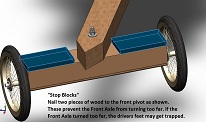 Art from Virginia emailed me with this suggestion to have "stop blocks" on the front axle. These blocks act as a safety device to prevent the front axle from turing too far which could cause the kart to overturn, or which could trap a drivers feet causing injury. Click for Larger Image
Safety: Please note that without brakes - this go-kart can be very dangerous, and the Author accepts no responsbility for any hurt or injury caused. This go-kart is ideally suited for a grass park with no traffic.
Copyright: Please do not distribute these plans under a different name or ownership. Feel free to refer people to this website and/or link from your own website etc.
The Author of these plans and of this www.kartbuilding.net website would be interested in recieving any comments and suggestions. Please use the following email address:

The above drawings and animations were done using the SolidWorks Modelling program, and took approximately 1 day to complete. Feel free to contact the Author for any further information.